Copyright 2012 neutronsources.org | All rights reserved. | Powered by FRM II | Imprint / Privacy Policy
Strain scanning from the surface into the bulk
01/07/2014
By J. Rebelo Kornmeier1, J. Saroun2, J. Gibmeier3 and M. Hofmann1
1Munich Technical University, FRM II, Garching, Germany
2Nuclear Physics Institute, ASCR, v.v.i., 25068 Řež, Czech Republic
3KIT – Karlsruhe Institute of Technology, IAM-WK, Kaiserstr. 12, 76131 Karlsruhe, Germany
Neutrons are commonly used to probe residual strains from material volumes in depths of several millimetres under the sample surface. However, neutron strain analysis is problematic at regions near a surface, as aberration peak shifts arise, which can be of the same order as the peak shifts related to residual strains. A new analytical model for the surface effect has been developed. This model permits to predict the spurious peak shifts and also provides optimum instrumental configuration parameters for a direct suppression of the surface effect.
Spurious strains
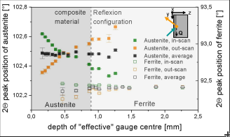
For non-destructive determination of the local triaxial residual stress distribution from the surface into the bulk of a component neutron diffraction offers the highest potential among the non-destructive diffracttions methods. With neutrons information depths of several millimeters in steel can be covered; for determination of near surface data through surface scanning must be carried out. However, the application of neutron radiation to determine the residual strain/stress gradient from the surface into the bulk is problematic as long as the gauge volume (GV) is not totally immersed in the material. Aberration peak shifts arise due to the fact that the GV being defined by the primary and secondary optics is partially outside the sample. These “virtual” shifts in strain, also called ‘spurious strains’ (see Fig. 1), may arise from the geometric, the wavelength spread and the peak clipping effects [1].
Various experimental approaches are proposed, like e.g. repetition of the through surface scan after flipping the sample for 180° as illustrated in Fig. 1, to compensate for the surface effect [2]. However, these experimental techniques have the drawback of being tremendously time consuming and are often simply impractical.
Minimization of spurious strains
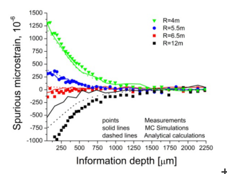
An alternative is the minimization of the surface effect by choosing an appropriate instrument configuration compensating for the surface effect in a self-consistent way. Modern neutron diffractometers for strain/stress analyses are often equipped with horizontally focusing monochromators, which allow tuning the resolution by simply varying the horizontal curvature. This is the method used at STRESS-SPEC to minimize the surface effects experimentally. Through surface scans at a stress free steel sample were carried out for different monochromator radii and different geometries in transmission and reflection mode and the resulting spurious strains were analysed (see Fig. 2).
The results showed that by setting the appropriate monochromator radius in combination with using a radial collimator at the diffracted beam side, the surface effects can be almost entirely suppressed. This way direct measurements without any type of additional elaborate corrections can be conducted. A successful application for a shot penned steel sample is presented in [3].
Analytical model
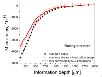
As a further development Monte Carlo (MC) numerical analysis was used as an efficient tool for simulation of the surface effect and optimization of the STRESSSPEC instrument configuration [4]. By this means spurious strains can be corrected for measurements carried out using a standard instrument setup, where large spurious strains can be expected. Further on the optimum instrument configuration for suppressing spurious strains can be predicted a priori. Measurements on a deep rolled steel sample using the standard setup but corrected for spurious strains were compared with direct measurements using the instrument setup for ´a priori´ spurious strain minimization (see Fig. 3). The data show excellent agreement and emphasize the applicability of the approach.
Moreover a novel analytical model [5] has been developed to universalise the prediction of the surface effect. This model covers a broad variety of instrumental arrangements, including flat mosaic and bent perfect crystal monochromators and narrow slits as well as Soller and radial collimators. The model is capable of accurate quantitative prediction of the surface effect.
The results obtained are encouraging for future routine use of this model for near surface strain/stress analysis on high flux neutron strain scanners like STRESS-SPEC.
We believe that the approach to model the surface strains accurately will enable to bridge the gap between bulk neutron measurements and data obtained using X-rays and/or synchrotron radiation.
Outlook: Applying the analytical model to engineering problems
Based on the instrument development presented here various industrial applications have been successfully realized. Further, within the scope of a research project between the Institute of Applied Materials (KIT) and FRM II funded by the German Research Foundation (DFG HO 3322/2-1|GI 376/5-1) first analysis for laser hardened steel were provided. Stationary laser surface hardening results in a local martensitic hardened lens with a depth of about 1 mm, which is embedded in ferritic/bainitic base material. The conventional approach for residual stress depth analysis is using lab X-ray diffraction in combination with electrochemical polishing. However, the local layer removal causes redistributions of the local residual stresses and hence, the original stress profile cannot be provided this way. The analysis must be accompanied by elaborate simulations of the redistribution effect. Non-destructive analysis can overcome this deficiency. Here, through surface neutron strain scanning provides a promising alternative.
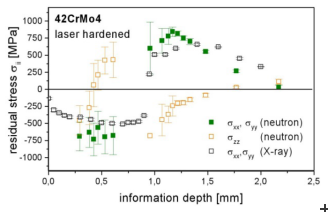
Figure 4 shows first results of the residual stress depth profile in the martensitic process zone and in the base material. Neutron data were corrected/compensated for spurious strain at the very surface and at the interface between martensitic process zone and base metal.
The differences between the X-ray data and the neutron results are inter alia due to local redistributions of residual stresses caused by the local layer removal that must be applied to gain access to the measurement location.
[1] Webster, P. J., Mills, G., Wang, X.D., Kang, W.P. and Holden, T.M. (1995) J. Neutron Res. 3 223–40
[2] Hutchings, M.T., Withers, P.J., Holden, T.M., Lorentzen, T., Introduction to the Characterizationof Residual Stress by Neutron Diffraction, Taylor and Francis, London (2005)
[3] Kornmeier, J.R., Gibmeier, J. & Hofmann, M. (2011). Meas. Sci. Technol. 22, 065705
[4] Kornmeier, J. R., Saroun, J., Gibmeier, J. & Hofmann, M. (2014) Mater. Sci. Forum. 768-769, 52-59
[5] Saroun, J., Kornmeier, J.R., Hofmann, M., Mikula, P., Vrana, M. J. Appl. Cryst. (2013) 46, 628–638


